 The
assembly of Soft66DB ,EASY SOLDERING! The
assembly of Soft66DB ,EASY SOLDERING!
Soft66DB adds the band path filter which used the Troid
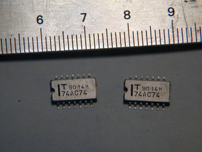
core for Soft66D. 74HC(s)74 of devider are changed into
74AC74, and TC4066 of a mixer is changed into 74HC(s)4066.
The frequency band which can respond was not only extended,
but sensitivity is improved by change of a mixer chip. If an
office dispatch number can be poured in well, it is the
specification which can use even a 28MHz belt.
Center frequency is 7.056MHz(NEW).
Since the assembly is using the DIP parts and the usual
part, there is no difficult to solder them by hand. In the
portion which rolls a coil, since the bifiler coil is
carried out, if cautions remove a required point for a
while, a soldering beginner should be able to also assemble
easily. Although UEW melts and it should be able to solder
with the heat of solder iron, since 0.32attached UEW line
does not melt in iron with small capacity, it is necessary
to polish it by sandpaper beforehand.
A
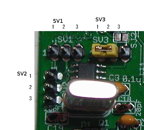
shematics and part arrangement
It is a shematic. It will become large if it clicks.

It is a part arrangement plan. It will become large if it
clicks. Since a jumper wire is under 74AC74 and an
operational amplifier, please wire first(red line is
jumper).

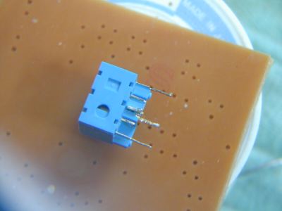
It is the home made PCB contained in a kit.

Please wire jumper first.
Example construction.kits is not include ANT pin and V+
pin.

New PCB and Parts
 click enlarge


How
to roll a band path filter
Please coil a UEW line around a core first. If it winds
in order of L2, L3, and L1, a PEW line should be able to be
used up well. Respectively required length and a
respectively required number of turns are as follows (the
following data is an object for 7M belts.). About 3.5M, 14M,
and 21M, a number of turns and the capacity of a capacitor
are due to be raised one by one.
7Mband
L2 14T(T30-6,yellow)、12T(T30-2,red)
L3 33T(T30-6,yellow)、30T(T30-2,red)
L1 bifiler14T (T30-6,yellow)、12T(T30-2,red)
C10,C15= 220pF + 680pF
C11=120pF
3.5M & 7Mband
L2 20T(T30-6,yellow)、19T(T30-2,red)
L3 33T(T30-6,yellow)、30T(T30-2,red)
L1 bifiler 20T(T30-6,yellow)、19T(T30-2,red)
C10,C15= 100pF + 680pF
C11=220pF+100pF
The state which rolled L2

L3

Since L1 is bifiler, it turns up and twists a PEW line.
If it turns to a finger round and round through one of the
two, it can twist easily.

Please coil the twisted line 14 times and confirm an
electrical connection, respectively.

It will be easy to solder if the end of the PEW line of
the core which it finished rolling is polished by
sandpaper.
Please set C11 150pF and C15,C16 1000pF to make BPF zone
large.
Please set C11 120pF and C15,C16 800pF to make BPF zone
narrow.
Description
of including parts
It is description of the part attached to a kit. It may
change without a preliminary announcement into other
parts.
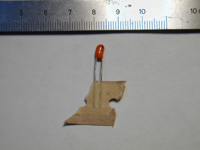
The 0.1uF tantalum capacitor of C14, C4, C5, C3, and C2.
The one where a leg is longer is +. It is small written as
104.

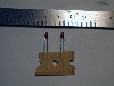
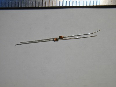
C11,100pF ceramic capacitor. 150pF may be contained.

C15, C16 or 1000pF ceramic capacitor. 680pF may be
contained.

The tantalum capacitor of C1. The one where a leg is
longer is +.
The tantalum capacitor of C12 and C13. Please turn + with
a longer leg to an operational amplifier side.
Operational amplifier. NJM2068DD of JRC.

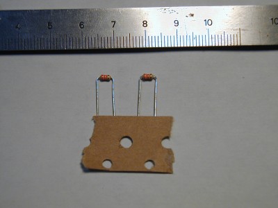
The laminating ceramic capacitor of C8 and C9.

74AC74 (it is careful in the direction which applying
cuts.) It is a very confusing chip.
74HC4066

T30-6

5.1k of R5 and R6. There is also a case of 4.7k.
2.2k of R7 and R8. There is also a case of 3.3k.
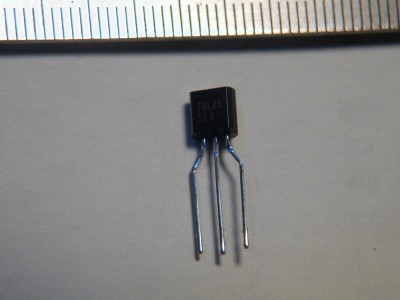
78L05
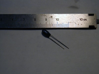
The tantalum capacitor of 47uF(s). The one where a leg is
longer is +.
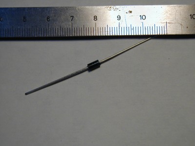
The diode for rectification of 400V1A
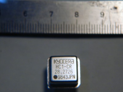
OSC(change to daughter board with 28.224MHz crystal
resonator)
Earphone jack. Please cut two inside legs with nippers.
Please make the remaining legs straight on radio pliers.
The ceramic capacitor of supplementary 0.1uF. Since the
frequency characteristic is good, it may put in instead of
tantalum.

It connects with a personal computer and recieve.
Please check whether it is correct to connection of
better [ in the end of an assembly ] た et al. and
parts. An antenna is connected with ANT. Although it
connects with the sound card of a personal computer, since
the microphone input is a monophonic recording, please
connect almost all sound cards with the line in of a stereo
input.
Download of SDR
radio
It is click in the middle of this homepage. Since it is
with here, it clicks and downloads. It will be installed if
the downloaded file is performed. If SDRadio is started,
please connect a power supply with an experiment circuit. A
push on the lower left RX button starts reception.
Download Rocky
It seems that Rocky is suitable when receiving amateur
radio. Compared with SDRadio, receiving sound can be heard
quite firmly. But it is very easy to hear the Morse
code.
When the signal reversed in the contrastive position can
be heard, please adjust the balance of line in. Moreover,
the whole noise level also falls by adjusting the level of
line in.
|


