Please visit my page.Assembled New Soft66AD is arriving. New Soft66Lite kit is released now.
SOFT66RF
Features
- 4 band pass filter on PCB(basic type has one BPF for 40m band)
- Balan for SWL(optional)
- all parts are lead type.
- more sensitivity on higher band with RF amplifire on PCB.
- connectivity with DDS-34andDDS-BASE
 NOTE:SMA Jack is
not including.
NOTE:SMA Jack is
not including.
-
Soft66RF is newest version of Soft66 series. Soft66RF have 4 band pass
filter with micro inductor.You do not need to wind troido core.It
is
easy assembling. Default frequency is 7.056MHz.Please ask me another frequency.
example: you want to recieve 7.02MHz ->28.08MHz
14.12MHz 14.7456MHz 16.9344MHz 20.0MHz 22.684MHz 28.08MHz 28.12MHz
28.16MHz 28.6363MHz 3.520MHz 42.8MHz 43.1MHz 43.4MHz 50.150MHz
56.448MHz 7.003MHz 7.005MHz 7.01MHz($2USD each)
Soft66RF have 2 type of power line. NJM2068 is working at 9V. It is
more clear signals. Soft66RF is more sensitive with J310 RF amplifire
at high band.
Connecting DDS-34 or DDS-BASE, Soft66RF become powerfull SW radio up to
30MHz. If you select DDS-BASE, there is less spurius.
you can use long wire antenna adding balan on PCB for SWL user. It is
very usefull on AM receiving.
If you have question. please mail to ja7tdo<atmark>zao.jp
Soft66 is one of the GAS
project.SOFT66is release on open source design.
ORDER PAGE
JA7TDO
Kazunori Miura
schematics
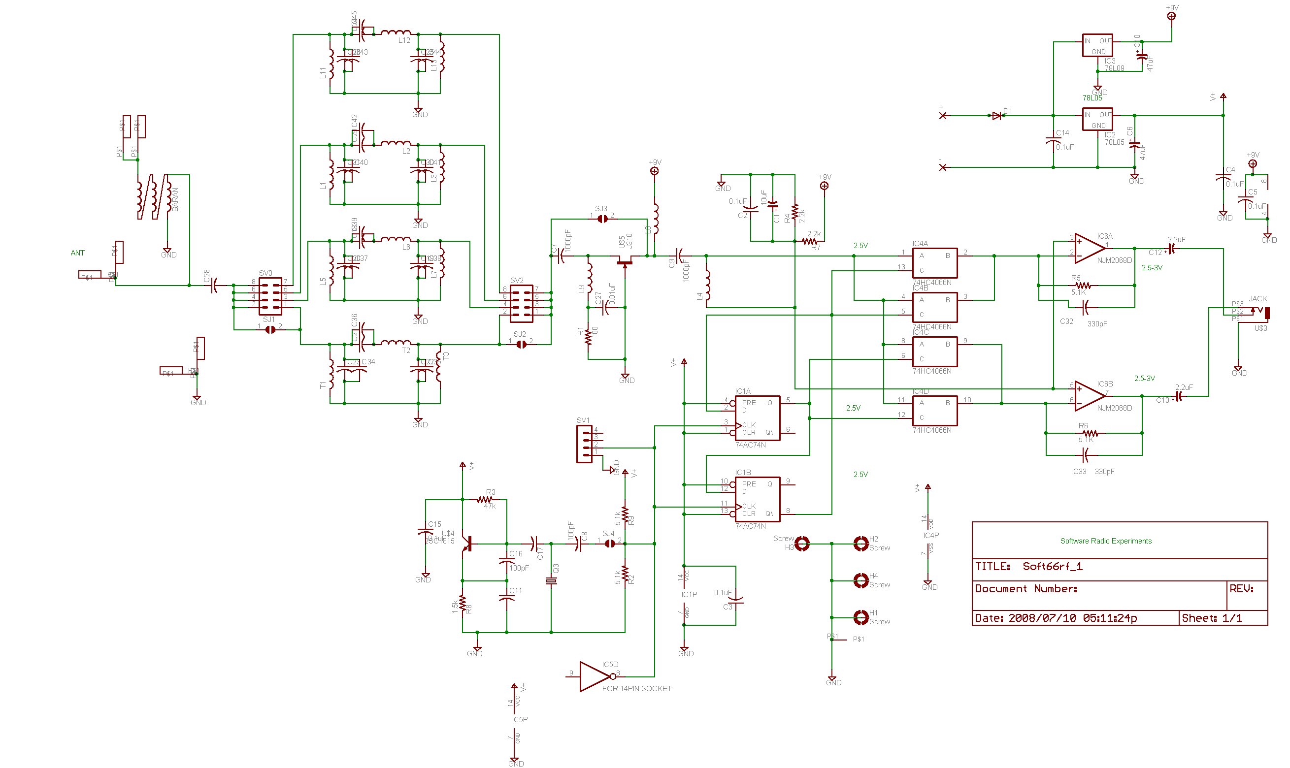 right click for
large image
right click for
large image
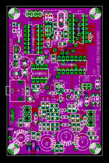
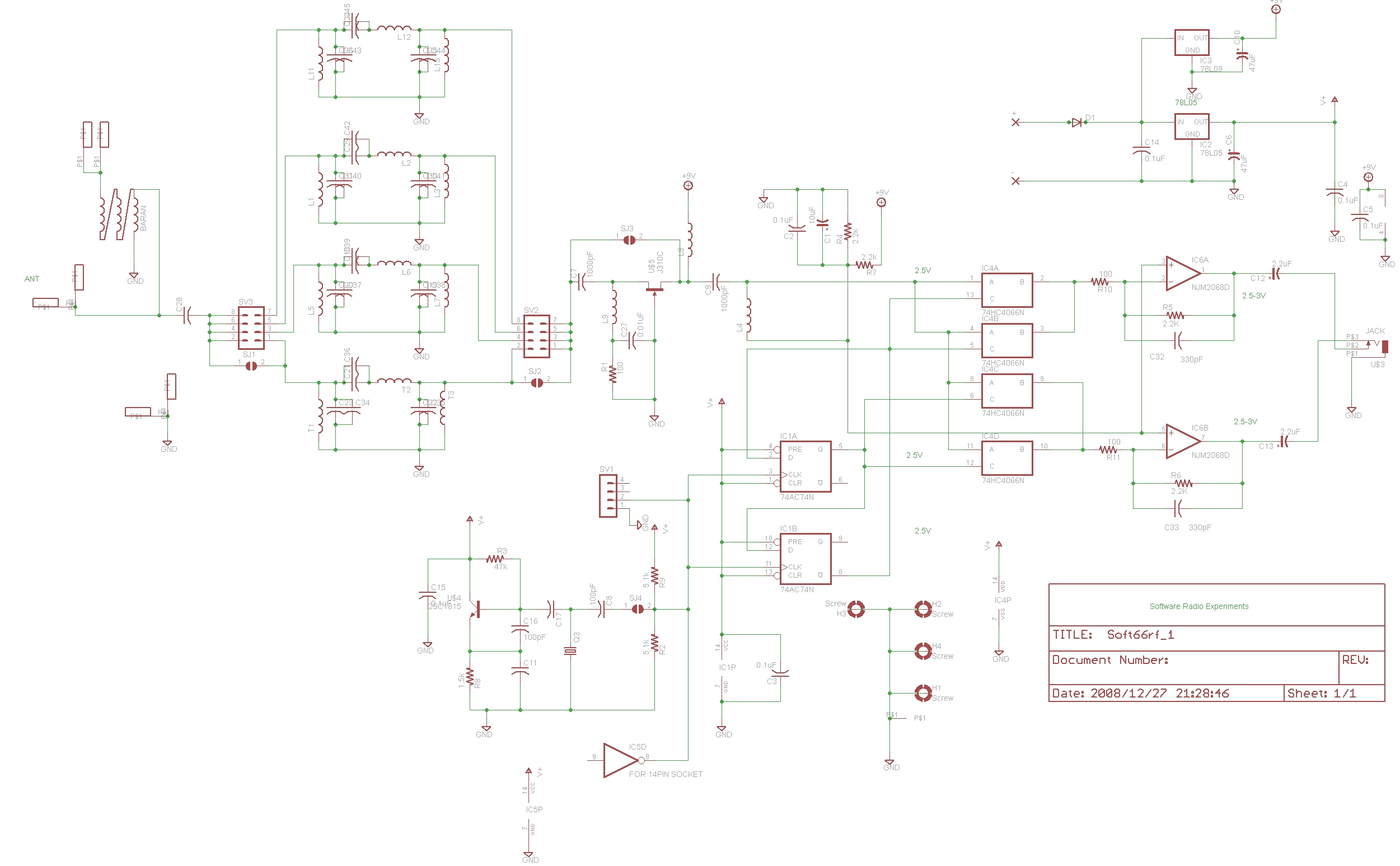 new version(red pcb)
attatch DDS-34B to Soft66RF
first, insert 14pin IC socket into IC5. second, remove solder of SJ4.
instruction for Soft66RF(basic type)
1.Check your packing
Please check your packet according to PartsList.
2.setting jumper
first, please jumper ON with solder side of PCB.
Please jumper ON SJ4.
If you receive low band, I reccomend you SJ3 is ON. It is no need to
build RF block.
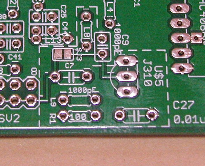
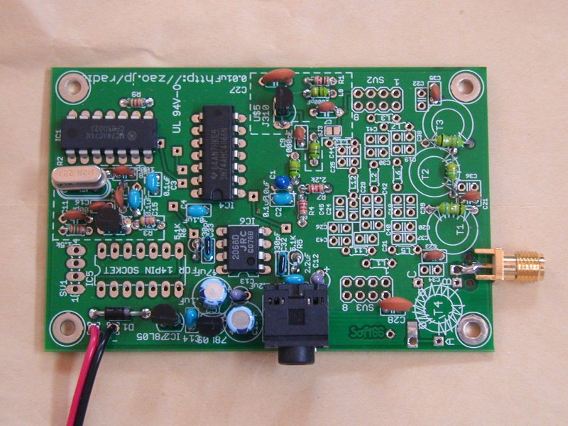
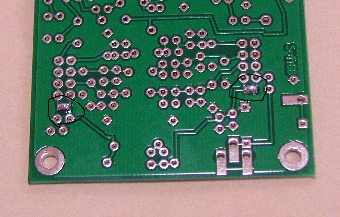
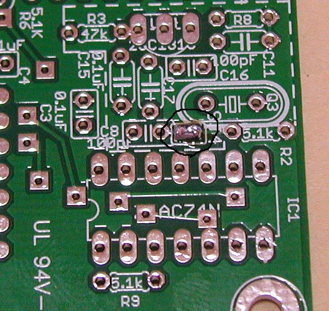
3.Assembling
Please assemble components according to this image.You can look larger
image with right click and view image.
Please note SMA Jack is NOT
including.
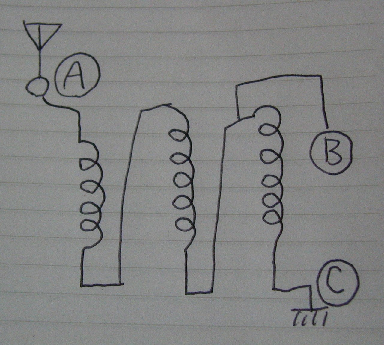
You can add balan for long wire antenna. Please use T37-43. winding 11 turns with
0.23mm or 0.26mm wire to trifiler.
A,B,C is silk mark on PCB.
4.Connecting to PC
Please connecting Jack to your PC Line input. Plug DC power about 12V
to 20V.
You need also install Rocky or
SDRadio.
5.optional BPF
It is enable to add optional 3BPF on Soft66RF.Please look inductor and capacitor value.
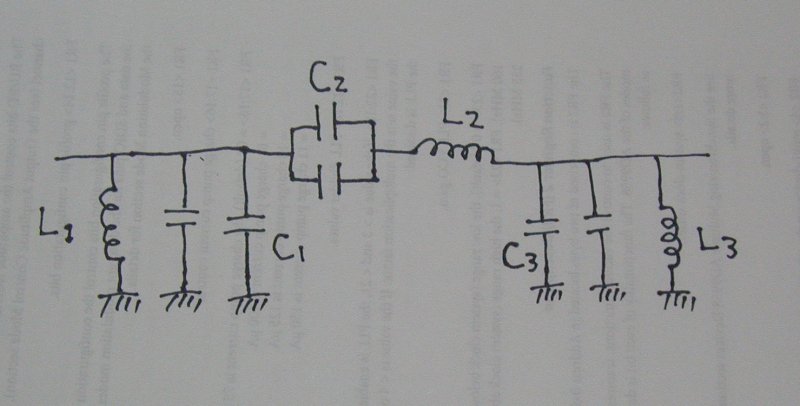
middle wave:400kHz〜1600kHz(L1,L3->5.6uH L2->26uH(22uH+5.6uH) or 27uH C1,C3->5600pF C2->1000pF)
160m:(L1,L3->2.2uH L2->16uH(10uH+5.6uH) C1,C3->3300pF C2->470pF)
80m:(L1,L3->2.2uH L2->5.6uH C1,C3->1000pF C2->470pF)
20m:(L1,L3->0.27uH L2->3.3uH C1,C3->680pF C2->40pF(20pF+20pF))
15m:(L1,L3->0.27uH L2->2.7uH(2.2uH+0.47uH) C1,C3->560pF C2->20pF)
PartsList
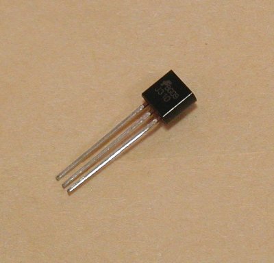
U$4 2SC1815 or
2SC1674

IC4 74AHC4066 or 74VHC4066 or 74HC4066
IC1
74AC74
IC2 78L05
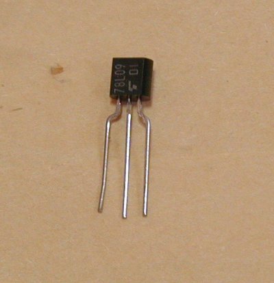
IC3 78L09
BPF parts C23,C22=1000pFx2 or (680pF + 220pF) x 2 ,C21=100pF or 120pF,T2=6.8uH or
5.6uH,T1,T3=0.68uHx2 or 0.47uH 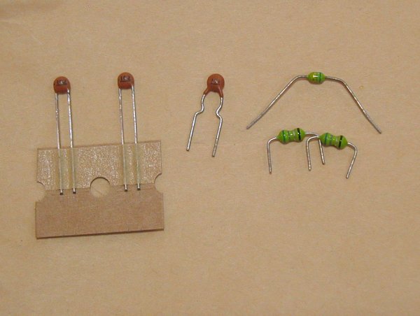
C27,C28 0.01uF(103)
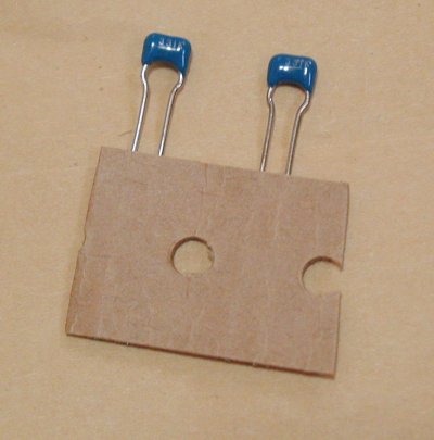
Ceramic Capacitor 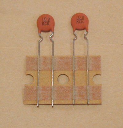
C2,C3,C4,C5,C14,C15 0.1uF(104)
Ceramic Capacitor 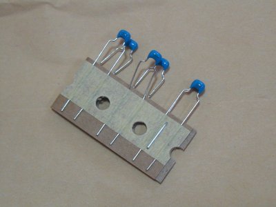
C7,C9 1000pF or 680pF
Ceramic Capacitor 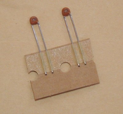
C8,C11,C16,C17 100pF or 120pF Ceramic Capacitor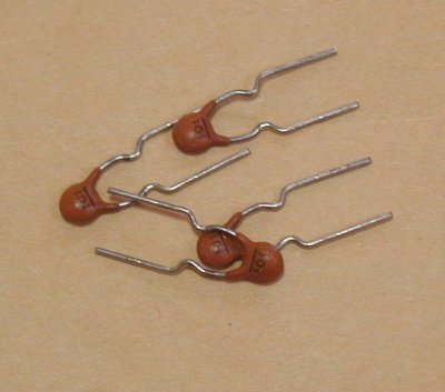
C1 10uF or 2.2uF
tantalum capacitor 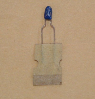
C12,C13 1uF(105) or 2.2uF or 3.3uF
capacitor 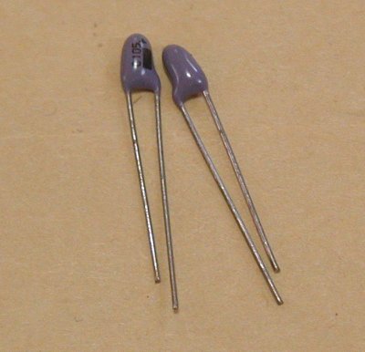
C32,C33 330pF Ceramic
Capacitor
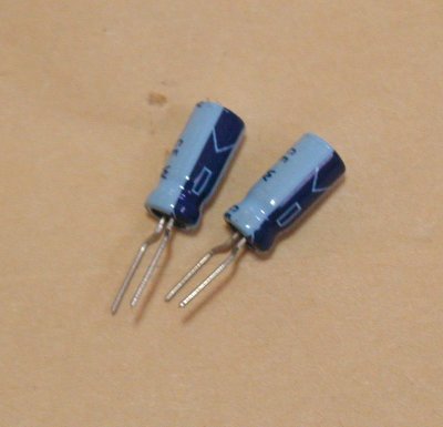
C6,C10 47uF
electrolysis capacitor
D1 1N4004
diode 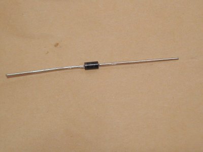
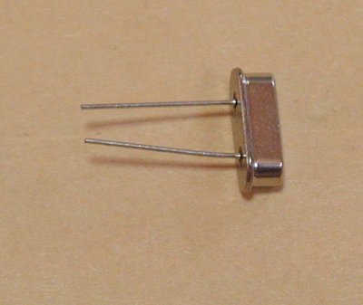
Q1 HC49US crystal resonator
L9 1uH inductor
L4,L8 22uH or 47uH
inductor 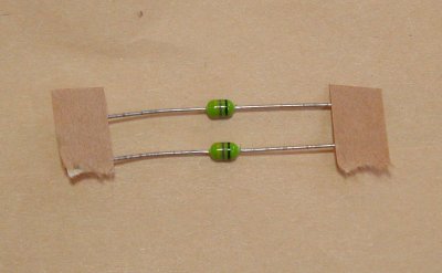
U$5 J310 or 2SK192
RF増幅
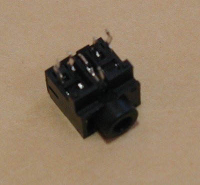
JACK
please cut inside pins
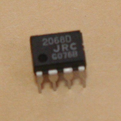
IC6 NJM2068D
operational amplifiere
R1,R8 1.5kΩ
register If you need more gain, R1 is 100 ohm.
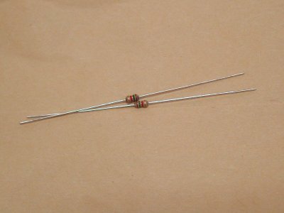
R10,R11 -> 100ohm
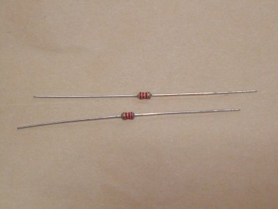
R4,R7 2.2kΩ
register
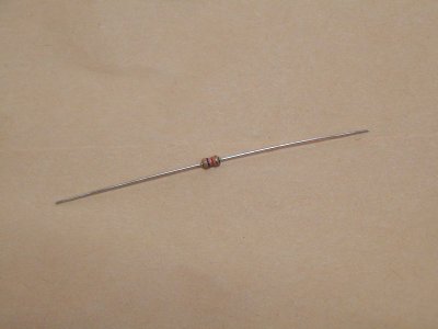
R3 47kΩ
register
R2,R9,R5,R6 5.1kΩ
register
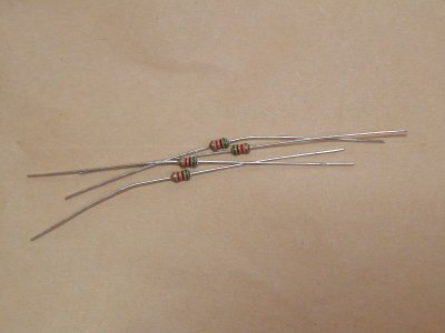
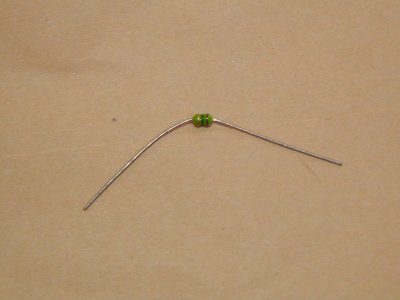
LINK inductor
color code